APPROACH AND OUTCOMEs
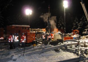
Aquatech responded immediately, attending the site to preform multiple tests and gather all required information to provide the client with a plan of action to mitigate the current design issues. Once Aquatech completed the assessment and submitted the findings report to the client with recommendations, the client decided to give Aquatech a chance at supplying the right equipment for the job, performing the correct installation and maintenance on the system for the remining period of the job.
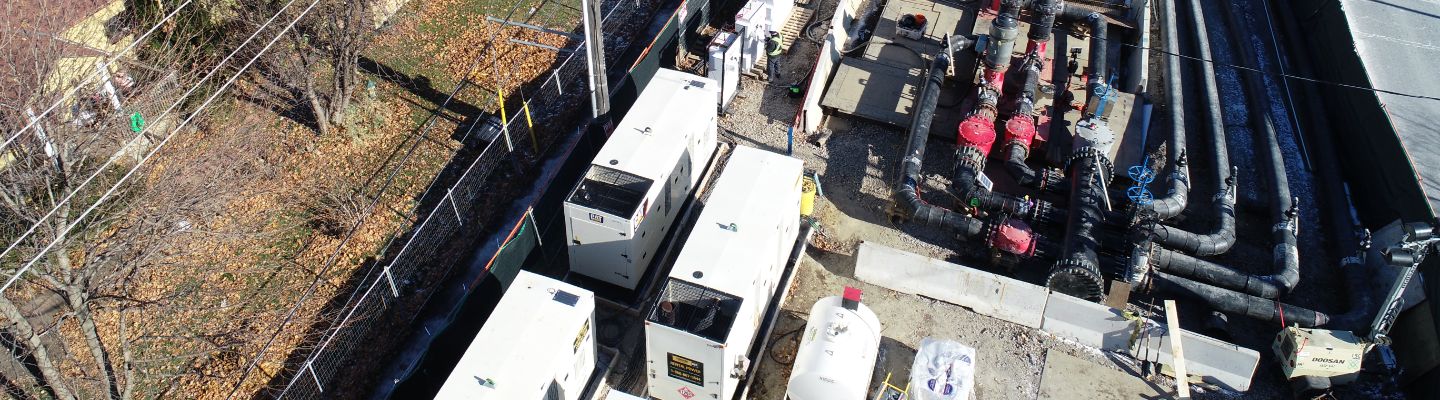
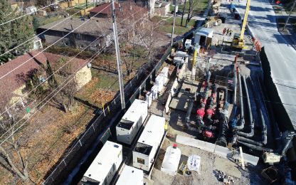
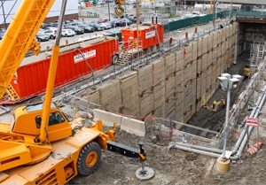
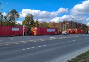
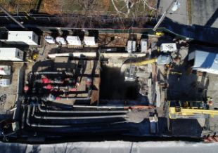
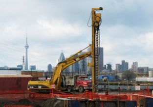
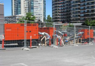
Aquatech immediately responded with a complete system design calculation, detailed layout and quotation; within less than two weeks, Aquatech had a one-of-a-kind in Canada bypass system installed and pumping as per tender specifications and City of Toronto specifications. The proposed bypass system consisted of four (4) 18” Vertical Turbine pumps (three primary and one backup) capable of handling 4” solids. Each pump is equip with a custom-made chopper blade to prevent the pumps from clogging while pumping sewage. Two (2) pumps were supplied complete with 250HP motors and the other two (2) pumps were supplied with 400HP motors. The higher horsepower pumps are be capable of rotating at higher speed resulting in higher flow and head capacity. The pumps were mounted on two custom designed and manufactured mounting plates located at the top of the shaft. Each pump was supplied with a 20m (65ft) long shaft to extend from the mounting plate (where the electric motor is mounted) down and inside the concrete sewer line.
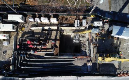
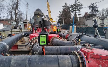
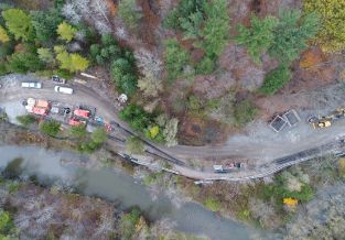
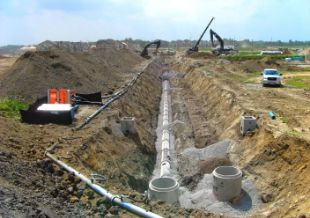
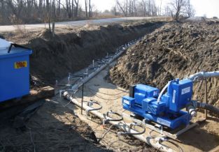
An 18” DR17 HDPE pipe was supplied to connect between each pump’s discharge flange to a common manifold. The
manifold was connected to four (4) 18” HDPE discharge piping to convey the bypass flow to the discharge locations.
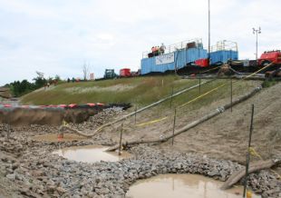
Each pump was supplied with a dedicate diesel generator and a VFD control panel. The VFD panel can be used to control the pump speed to achieve the most efficient operating point based on the influent flow rates.
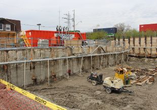
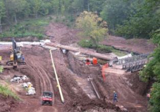
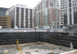
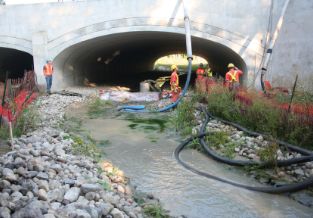
The system was installed and operational for approximately two months to the end of the project, Aquatech was able to give the contractor the dry conditions he need to perform this job on time and seamlessly as per plan.
In addition to the above challenges, Aquatech was able to identify multiple design/installation flaws with the current installed system and provided a mitigation plan for each. Below is a summary of findings;
- Inadequate capacity to handle the dirty sewer. The contractor was experiencing major “clogging” to their bypass pumps resulting in reduced total flow capacity of the bypass system.
- Improper installation of the bypass pumps by not allowing enough critical submergence and enough separation between the pump’s intake lines. This also majorly impacted the output of each pump.
- Air and Vacuum relief valves were not installed in the proper location allowing for air to be entrapped at high points on the discharge line. This is another issue usually overlooked by some pumping system designers. Entrapped air in a pipeline results in erratic pump operation and increased head resulting in reduced pump performance.
- Lack of system data to be able to trouble shoot a problem. Unfortunately, the system was installed without the use of pressure gauges, flow meters and/or level transducers.
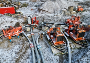
- The pumping system provided by the other contactor did not have a maintenance program in place to ensure all preventive maintenance is competed on time. This is a major issue for a large pumping system that included seven (7) hydraulic submersible pumps each with a separate powerpack, hydraulic hoses etc.
- Cables, engines, pumps and hydraulic oil lines were not properly marked which made it very difficult to identify which pump is connected to which powerpack.